Hardware Instructions
- Please prepare the following units
- LinkIt One development board (including battery, GPS antenna, and WiFi antenna)
- PMS3003 (G3) dust sensor x 1
- Note that the all-in-one package (including everything above) is available in the following links:
- (ebay) LASS Field Try Package
- (iCshop) LASS Field Try Package

- Linkit ONE HW block diagram:

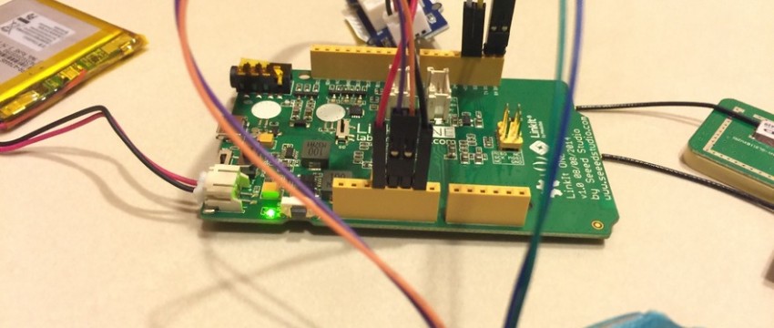
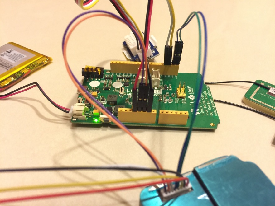
- Please connect the battery, GPS receiver (the square one), and WiFi antenna (the thin rectangle one) to the LinkIt One board. You will find small text under the connectors noting GPS and WiFi on the board.
- Please refit the 1st (purple), 2nd (orange), and 5th (green) wiring of the G3 sensor iknto the Dupont connector. (If you buy the all-in-one package from the above link, you can skip this step).
- Please connect the following wirings of the G3 sensor to the corresponding pins on the LinkIt One board:
- the 1st (purple) wiring to the 5V pin;
- the 2nd (orange) wiring to the GND pin; and
- the 5th (green) wiring to the Rx pin.

- Please connect the following wirings of the Grove – Temperature and Humidity Sensor Pro to the corresponding pins on the LinkIt One board:
- the 1st (yellow) wiring to the D2 pin;
- the 2nd (white) wiring to the D3 pin (this wiring is NOT used, and may have been removed in the all-in-one package provided in the above link);
- the 3rd (red) wiring to the 3V3 pin; and
- the 4th (black) wiring to the GND pin.

- Now, the hardware is ready to work! Feel free to adjust the sensor and antenna to your favorite relative positions. You can also find a good cover/enclosure for your set. If you have a 3D printer, you may want to print out one of the existing design from the LASS archive (https://github.com/LinkItONEDevGroup/LASS/tree/master/3dp).

Software Instructions
- If this your first time using LinkIt One, please refer to the official tutorial provided by MediaTek (MS Windows plafform、Mac OS platform). Note that, it is strongly recommend to use the Arduino IDE version indicated in the tutorial, otherwise you may experience a number of hardware related issues.
- Please goto GitHub and download the latest version LASS codes: LASS.ino and configuration.h
- Please install the following libraries (from here) into your Arduino environment. In case you have trouble installing libraries into your Arduino environment, you may find this tutorial useful: Installing Additional Arduino Libraries.
- Grove – Temperature and Humidity Sensor Pro: DHT_linkit.zip
- KalmanFilter: HP20x_dev.zip
- Under Arduino IDE, please open the LASS.ino project, and edit the configuratin.h file as follows:
- #define APP_ID (APPTYPE_SYSTEM_BASE+X): please change ‘X’ to ‘1’
- #define WIFI_SSID “LASS”: please change “LASS” to your WiFi SSID
- #define WIFI_PASS “LASS123456”: please change “LASS123456” to your WiFi password (you can skip this step if there is no WiFi password)
- #define WIFI_AUTH LWIFI_WPA: please keep it as it is (if you are using WPA encryption), or change it to “LWIFI_WEP” (if you are using WEP encryption) or “LWIFI_OPEN” (if there is no encryption used)
- Now, the software is ready to go! Please compile the codes and upload to your LinkIt One board. (please make sure the board is connected to your PC).
Testing
- The simpliest way is to use the link: http://nrl.iis.sinica.edu.tw/LASS/show.php?device_id=FT1_001. Please replace FT1_001 with your device ID (as configured in the above section), and you should be able to see a dashboard showing the current sensor values of your own device.
- You can also find the GIS visualization of your device at your location:
- LASS also provides a number of approaches to access the measurement data of your device and other device. For more detailed information, please check out the webpage: LASS Data Platform
FAQ
- Where can I find help if I need technical help?
- You are welcome to post on LASS FB. Please do remember to include the error messages and other useful information so people in the community can help you.
- You are also encouraged to help maintain this page, and make it more helpful for people in the LASS community.