| /*
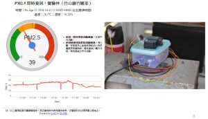
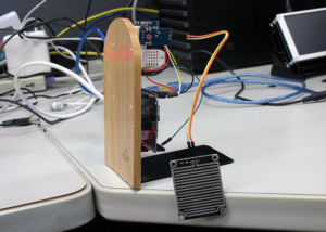
This example demonstrate how to read pm2.5 value on PMS 3003 air condition sensor
PMS 3003 pin map is as follow:
PIN1 :VCC, connect to 5V
PIN2 :GND
PIN3 :SET, 0:Standby mode, 1:operating mode
PIN4 :RXD :Serial RX
PIN5 :TXD :Serial TX
PIN6 :RESET
PIN7 :NC
PIN8 :NC
In this example, we only use Serial to get PM 2.5 value.
The circuit:
* RX is digital pin 0 (connect to TX of PMS 3003)
* TX is digital pin 1 (connect to RX of PMS 3003)
*/
#include <math.h>
#define turnon HIGH
#define turnoff LOW
#define DHTSensorPin 7
#include “PMType.h”
#include <WiFi.h>
#include <WiFiUdp.h>
#include <Wire.h> // Arduino IDE 內建
// LCD I2C Library,從這裡可以下載:
// https://bitbucket.org/fmalpartida/new-liquidcrystal/downloads
#include “RTClib.h”
RTC_DS1307 RTC;
//DateTime nowT = RTC.now();
#include “DHT.h”
// Uncomment whatever type you’re using!
//#define DHTTYPE DHT11 // DHT 11
#define DHTTYPE DHT22 // DHT 22 (AM2302), AM2321
//#define DHTTYPE DHT21 // DHT 21 (AM2301)
#include <LiquidCrystal_I2C.h>
#include <SoftwareSerial.h>
uint8_t MacData[6];
SoftwareSerial mySerial(0, 1); // RX, TX
char ssid[] = “TSAO”; // your network SSID (name)
char pass[] = “TSAO1234″; // your network password
#define MAX_CLIENT_ID_LEN 10
#define MAX_TOPIC_LEN 50
char clientId[MAX_CLIENT_ID_LEN];
char outTopic[MAX_TOPIC_LEN];
IPAddress Meip ,Megateway ,Mesubnet ;
String MacAddress ;
int status = WL_IDLE_STATUS;
boolean ParticleSensorStatus = true ;
WiFiUDP Udp;
const char ntpServer[] = “pool.ntp.org”;
const long timeZoneOffset = 28800L;
const int NTP_PACKET_SIZE = 48; // NTP time stamp is in the first 48 bytes of the message
const byte nptSendPacket[ NTP_PACKET_SIZE] = {
0xE3, 0x00, 0x06, 0xEC, 0x00, 0x00, 0x00, 0x00, 0x00, 0x00, 0x00, 0x00, 0x31, 0x4E, 0x31, 0x34,
0x00, 0x00, 0x00, 0x00, 0x00, 0x00, 0x00, 0x00, 0x00, 0x00, 0x00, 0x00, 0x00, 0x00, 0x00, 0x00,
0x00, 0x00, 0x00, 0x00, 0x00, 0x00, 0x00, 0x00, 0x00, 0x00, 0x00, 0x00, 0x00, 0x00, 0x00, 0x00
};
byte ntpRecvBuffer[ NTP_PACKET_SIZE ];
#define LEAP_YEAR(Y) ( ((1970+Y)>0) && !((1970+Y)%4) && ( ((1970+Y)0) || !((1970+Y)%400) ) )
static const uint8_t monthDays[]={31,28,31,30,31,30,31,31,30,31,30,31}; // API starts months from 1, this array starts from 0
uint32_t epochSystem = 0; // timestamp of system boot up
#define pmsDataLen 32
uint8_t buf[pmsDataLen];
int idx = 0;
int pm25 = 0;
uint16_t PM2_5Value=0; //define PM2.5 value of the air detector module
int NDPyear, NDPmonth, NDPday, NDPhour, NDPminute, NDPsecond;
unsigned long epoch ;
int HumidityData = 0 ;
int TemperatureData = 0 ;
LiquidCrystal_I2C lcd(0x27, 2, 1, 0, 4, 5, 6, 7, 3, POSITIVE); // 設定 LCD I2C 位址
DHT dht(DHTSensorPin, DHTTYPE);
void setup() {
Serial.begin(9600);
mySerial.begin(9600); // PMS 3003 UART has baud rate 9600
lcd.begin(20, 4); // 初始化 LCD,一行 20 的字元,共 4 行,預設開啟背光
lcd.backlight(); // 開啟背光
MacAddress = GetWifiMac() ;
ShowMac() ;
initializeWiFi();
initRTC() ;
ShowDateTime() ;
ShowInternetStatus() ;
delay(1500);
}
void loop() { // run over and over
ShowDateTime() ;
retrievePM25Value() ;
ShowHumidity() ;
delay(1000); // delay 1 minute for next measurement
}
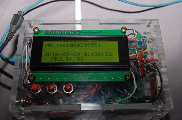
void ShowMac()
{
lcd.setCursor(0, 0); // 設定游標位置在第一行行首
lcd.print(“MAC:”);
lcd.print(MacAddress);
}
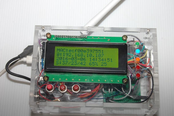
void ShowInternetStatus()
{
lcd.setCursor(0, 1); // 設定游標位置
if (WiFi.status())
{
Meip = WiFi.localIP();
lcd.print(“@:”);
lcd.print(Meip);
}
else
{
lcd.print(“DisConnected:”);
}
}
void ShowPM25(int pp25)
{
lcd.setCursor(0, 3); // 設定游標位置在第一行行首
lcd.print(“PM2.5: “);
lcd.setCursor(9, 3); // 設定游標位置在第一行行首
lcd.print(pp25);
}
void ShowDateTime()
{
// getCurrentTime(epoch, &NDPyear, &NDPmonth, &NDPday, &NDPhour, &NDPminute, &NDPsecond);
lcd.setCursor(0, 2); // 設定游標位置在第一行行首
lcd.print(StrDate());
lcd.setCursor(11, 2); // 設定游標位置在第一行行首
lcd.print(StrTime());
// lcd.print();
}
String StrDate() {
String ttt ;
//nowT = now;
DateTime now = RTC.now();
ttt = print4digits(now.year()) + “-” + print2digits(now.month()) + “-” + print2digits(now.day()) ;
//ttt = print4digits(NDPyear) + “/” + print2digits(NDPmonth) + “/” + print2digits(NDPday) ;
return ttt ;
}
String StringDate(int yyy,int mmm,int ddd) {
String ttt ;
//nowT = now;
ttt = print4digits(yyy) + “-” + print2digits(mmm) + “-” + print2digits(ddd) ;
return ttt ;
}
String StrTime() {
String ttt ;
// nowT = RTC.now();
DateTime now = RTC.now();
ttt = print2digits(now.hour()) + “:” + print2digits(now.minute()) + “:” + print2digits(now.second()) ;
// ttt = print2digits(NDPhour) + “:” + print2digits(NDPminute) + “:” + print2digits(NDPsecond) ;
return ttt ;
}
String StringTime(int hhh,int mmm,int sss) {
String ttt ;
ttt = print2digits(hhh) + “:” + print2digits(mmm) + “:” + print2digits(sss) ;
return ttt ;
}
String GetWifiMac()
{
String tt ;
String t1,t2,t3,t4,t5,t6 ;
WiFi.status(); //this method must be used for get MAC
WiFi.macAddress(MacData);
Serial.print(“Mac:”);
Serial.print(MacData[0],HEX) ;
Serial.print(“/”);
Serial.print(MacData[1],HEX) ;
Serial.print(“/”);
Serial.print(MacData[2],HEX) ;
Serial.print(“/”);
Serial.print(MacData[3],HEX) ;
Serial.print(“/”);
Serial.print(MacData[4],HEX) ;
Serial.print(“/”);
Serial.print(MacData[5],HEX) ;
Serial.print(“~”);
t1 = print2HEX((int)MacData[0]);
t2 = print2HEX((int)MacData[1]);
t3 = print2HEX((int)MacData[2]);
t4 = print2HEX((int)MacData[3]);
t5 = print2HEX((int)MacData[4]);
t6 = print2HEX((int)MacData[5]);
tt = (t1+t2+t3+t4+t5+t6) ;
Serial.print(tt);
Serial.print(“\n”);
return tt ;
}
String print2HEX(int number) {
String ttt ;
if (number >= 0 && number < 16)
{
ttt = String(“0″) + String(number,HEX);
}
else
{
ttt = String(number,HEX);
}
return ttt ;
}
String print2digits(int number) {
String ttt ;
if (number >= 0 && number < 10)
{
ttt = String(“0″) + String(number);
}
else
{
ttt = String(number);
}
return ttt ;
}
String print4digits(int number) {
String ttt ;
ttt = String(number);
return ttt ;
}
// send an NTP request to the time server at the given address
void retrieveNtpTime() {
Serial.println(“Send NTP packet”);
Udp.beginPacket(ntpServer, 123); //NTP requests are to port 123
Udp.write(nptSendPacket, NTP_PACKET_SIZE);
Udp.endPacket();
if(Udp.parsePacket()) {
Serial.println(“NTP packet received”);
Udp.read(ntpRecvBuffer, NTP_PACKET_SIZE); // read the packet into the buffer
unsigned long highWord = word(ntpRecvBuffer[40], ntpRecvBuffer[41]);
unsigned long lowWord = word(ntpRecvBuffer[42], ntpRecvBuffer[43]);
unsigned long secsSince1900 = highWord << 16 | lowWord;
const unsigned long seventyYears = 2208988800UL;
// epoch = secsSince1900 – seventyYears + timeZoneOffset ;
epoch = secsSince1900 – seventyYears ;
epochSystem = epoch – millis() / 1000;
}
}
void getCurrentTime(unsigned long epoch, int *year, int *month, int *day, int *hour, int *minute, int *second) {
int tempDay = 0;
*hour = (epoch % 86400L) / 3600;
*minute = (epoch % 3600) / 60;
*second = epoch % 60;
*year = 1970;
*month = 0;
*day = epoch / 86400;
for (*year = 1970; ; (*year)++) {
if (tempDay + (LEAP_YEAR(*year) ? 366 : 365) > *day) {
break;
} else {
tempDay += (LEAP_YEAR(*year) ? 366 : 365);
}
}
tempDay = *day – tempDay; // the days left in a year
for ((*month) = 0; (*month) < 12; (*month)++) {
if ((*month) == 1) {
if (LEAP_YEAR(*year)) {
if (tempDay – 29 < 0) {
break;
} else {
tempDay -= 29;
}
} else {
if (tempDay – 28 < 0) {
break;
} else {
tempDay -= 28;
}
}
} else {
if (tempDay – monthDays[(*month)] < 0) {
break;
} else {
tempDay -= monthDays[(*month)];
}
}
}
(*month)++;
*day = tempDay+2; // one for base 1, one for current day
}
void retrievePM25Value() {
int idx;
bool hasPm25Value = false;
int timeout = 200;
while (!hasPm25Value) {
idx = 0;
memset(buf, 0, pmsDataLen);
while (mySerial.available()) {
buf[idx++] = mySerial.read();
}
if (buf[0] == 0x42 && buf[1] == 0x4d) {
pm25 = ( buf[12] << 8 ) | buf[13];
Serial.print(“pm2.5: “);
Serial.print(pm25);
Serial.print(” ug/m3″);
Serial.println(“”);
hasPm25Value = true;
ShowPM25(pm25) ;
}
timeout–;
if (timeout < 0) {
Serial.println(“fail to get pm2.5 data”);
break;
}
}
}
void initializeWiFi() {
while (status != WL_CONNECTED) {
Serial.print(“Attempting to connect to SSID: “);
Serial.println(ssid);
// Connect to WPA/WPA2 network. Change this line if using open or WEP network:
status = WiFi.begin(ssid, pass);
// status = WiFi.begin(ssid);
// wait 10 seconds for connection:
delay(10000);
}
// local port to listen for UDP packets
Udp.begin(2390);
}
void printWifiData()
{
// print your WiFi shield’s IP address:
Meip = WiFi.localIP();
Serial.print(“IP Address: “);
Serial.println(Meip);
// print your MAC address:
byte mac[6];
WiFi.macAddress(mac);
Serial.print(“MAC address: “);
Serial.print(mac[5], HEX);
Serial.print(“:”);
Serial.print(mac[4], HEX);
Serial.print(“:”);
Serial.print(mac[3], HEX);
Serial.print(“:”);
Serial.print(mac[2], HEX);
Serial.print(“:”);
Serial.print(mac[1], HEX);
Serial.print(“:”);
Serial.println(mac[0], HEX);
// print your subnet mask:
Mesubnet = WiFi.subnetMask();
Serial.print(“NetMask: “);
Serial.println(Mesubnet);
// print your gateway address:
Megateway = WiFi.gatewayIP();
Serial.print(“Gateway: “);
Serial.println(Megateway);
}
void initRTC()
{
Wire.begin();
RTC.begin();
SetRTCFromNtpTime() ;
if (! RTC.isrunning()) {
Serial.println(“RTC is NOT running!”);
// following line sets the RTC to the date & time this sketch was compiled
// RTC.adjust(DateTime(__DATE__, __TIME__));
}
}
void SetRTCFromNtpTime()
{
retrieveNtpTime();
//DateTime ttt;
getCurrentTime(epoch+timeZoneOffset, &NDPyear, &NDPmonth, &NDPday, &NDPhour, &NDPminute, &NDPsecond);
//ttt->year = NDPyear ;
Serial.print(“NDP Date is :”);
Serial.print(StringDate(NDPyear,NDPmonth,NDPday));
Serial.print(“and “);
Serial.print(“NDP Time is :”);
Serial.print(StringTime(NDPhour,NDPminute,NDPsecond));
Serial.print(“\n”);
RTC.adjust(DateTime(epoch+timeZoneOffset));
}
void ShowHumidity()
{
float h = dht.readHumidity();
// Read temperature as Celsius (the default)
float t = dht.readTemperature();
// Read temperature as Fahrenheit (isFahrenheit = true)
float f = dht.readTemperature(true);
HumidityData = (int)h ;
TemperatureData = (int)t ;
Serial.print(“Humidity :”) ;
Serial.print(h) ;
Serial.print(“% /”) ;
Serial.print(t) ;
Serial.print(“C \n”) ;
// Check if any reads failed and exit early (to try again).
if (isnan(h) || isnan(t) || isnan(f)) {
Serial.println(“Failed to read from DHT sensor!”);
return;
}
lcd.setCursor(11, 3); // 設定游標位置在第一行行首
lcd.print((int)h);
lcd.print(“% “);
lcd.print((int)t);
}
|


