Yearly Archives: 2016

Home 2016
DSC_0863

UAV大氣剖面觀測系統

No Comments

專案動機 – 霧林的重要性

潮濕、涼爽、陰暗,是大部分人進入山地霧林的第一印象,山地霧林多半位於熱帶或亞熱帶臨海的山地區域,其特徵是每天週期性雲霧、以及充滿附生植物的森林樹冠層,由海岸來的潮濕空氣在沿著山地爬升之後,由於溫度下降,而形成濃厚雲霧帶。

霧林的獨特由於其水文特性 – 攔截雨霧,進而提升森林的涵水能力,但同時缺點也是因為倚賴霧水的水份供給,因此分布面積十分狹窄,此外由於山地霧林的獨特性,所以特有種比率非常高,許多物種只能生存在這樣的環境之中,在近年來氣候變遷下,有可能使雲霧帶生成高度上升,進而造成現有霧林帶乾旱的現象,最後使霧林帶的植物與特有種面臨威脅。

目前服務於國立臺灣大學實驗林管理處的賴彥任先生,以溪頭地區為例子,溪頭是著名的森林遊樂景點,因此長年有相當多的遊客照訪,到去年已經超過200萬的遊客,這還不包括去妖怪村等周遭景點但沒有進去溪頭自然園區的遊客數。也因此,我們也開始關注這麼多的遊客是否可能造成氣候與生態衝擊。

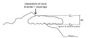
在南投溪頭發現了近幾年霧發生率快速減少的情況,因而提出UAV大氣剖面觀測的計劃,想藉由觀測雲霧的結構與時空分佈,進而分析雲霧的成因與導致雲霧快速減少的原因。

5591218236_f8412d5112

霧的觀測

霧通常採用能見度觀測,若能見度低於1KM則稱為起霧,我們也利用縮時攝影來觀測,但夜間是個問題。雲霧發生率通常有小時或日的統計,也就是若該觀測小時或日若有能見度低於1KM,則視為霧時或霧日,我們將霧日/365得上述的比例。

U1

觀測方法

1.安裝地點

由於溪頭是個峽谷的地形,道路也是沿著峽谷而上至溪頭,因此目前認為沿著路旁的國小放置裝置,計劃在雲林國小、初鄉國小、鹿谷國小、廣興國小、鳳凰國小、文昌國小、內湖國小、和雅國小、溪頭辦公室、溪頭天文台共10個點設置,主要是考量他們有電有網路。

U2

在固定的觀測點,系統會在沒有 Wifi AP 時自動記錄,等 Wifi 出現時,會自動連上線,將資料傳出來。所以只要定期走到設備旁邊,就可以將資料上傳到 server。U3

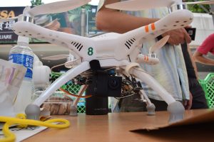
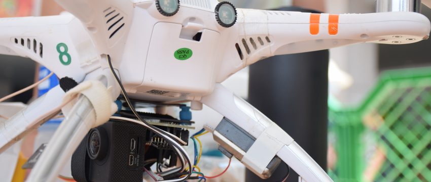
無人機天空感測,飛行過程中記錄資料,回來的時候就上傳,目前飛天感測感測是每五秒感測一次。

DSC_0847

感測點安裝完成之後,可以用比對觀測資料的方式,觀察雲霧形成的時間差。

2. 機構裝置

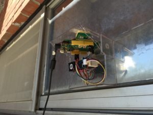
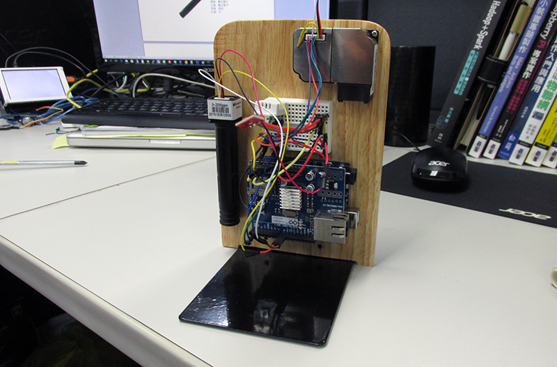
在原本的LASS觀測系統上進行改裝,需要將PM2.5感測器與濕度感測器(SHT31)放在標準的通風筒觀測。為能長期觀測設備會加入電瓶來長期供電,並加入Watchdog功能當系統有異常時執行重開機的能力。

Resource

DSC_0850

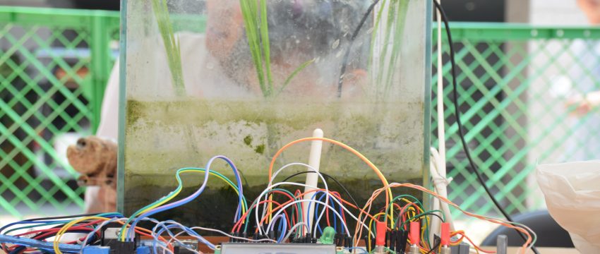
農業感測計畫Sensors for Farm

No Comments

緣起

LASS 是套環境感測器系統,經過社群的努力已整合感測設備、網路通訊連線與雲端資料庫,為追求其他突破,除了系統功能上的增強,也積極尋求其他相關領域的應用需求,突破目前LASS系統架構僅是應用在PM2.5空汙監控之上,此農業感測計劃便是將LASS環境感測的理念應用於農業之上。

大家都知道,農業是看天吃飯,這個『天』包括陽光、空氣、水,所以日照、溫、濕度、雨量土壤酸鹼度,這氣候氣象因素都會影響植物生長,而我們的農友可以透過獲得這些資訊,來創造適合生長的環境,以得到更好的收穫與農作品質。

114

計劃的實踐

  • 計劃的目標
  1. 產銷履歷氣候資料:加入當地農場的氣候資料到產銷履歷,目前市面上的產銷履歷提供有生產者與生產地的相關訊息,但這些資料對於消費者只能說是個保障,當出問題時利於追蹤到生產者,而不是一個選擇的依據,消費者在意的是這項商品是在什麼樣的情況下生產出來的,因此有加入氣候資料到產銷履歷的想法,由我們的機構收集數據整合於雲端系統(以彌補農場到鄰近氣象站的距離出產生的數值誤差)。
  2. 環境監控與預報:系統非常適合應用於溫室,以提供科學數據創造出作物良好的生長環境,而變因較多的戶外則是採專注於收集雨量資訊的策略,雨量常隨地理環境不同就有很大區別,氣象局預報的範圍還是太大,對於小區域性的農友不夠精確,山的一邊下雨,翻過山又是晴空萬里,因此可利用雨量數據做為土石流,淹水預警系統。
  • 應用區域:菜園、水田、魚菜共生
  • 系統功能概述:將農田的感測值用 LoRa 傳回來,在網頁或是 App 中顯示出來,並開放資料給大家取得。可以有效長期觀察農田的感測值變化,以及減少所需要的巡田次數

DSC_0849

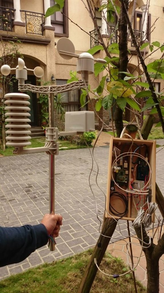
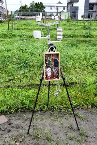
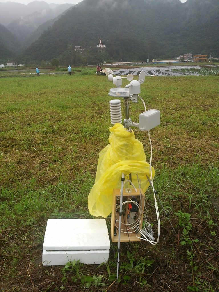
機構 – Weather Box

設計概念

  • 攜帶提箱式:Weather Box設計成提箱式讓使用者方便攜帶,可以便於記錄不同地區菜園的微氣候,並且附註在生產履歷上提供消費者參考。

lass.hackpad.com_c8meILUnsyi_p.525653_1452911709683_1452743523755

lass.hackpad.com_c8meILUnsyi_p.525653_1452911723895_1452743508415

  • 腳架可移動式:爲了快速架設風力、雨量感測器設計的移動型架構。

114-3
13389056_10205084860160112_1336685981_o

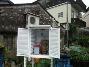
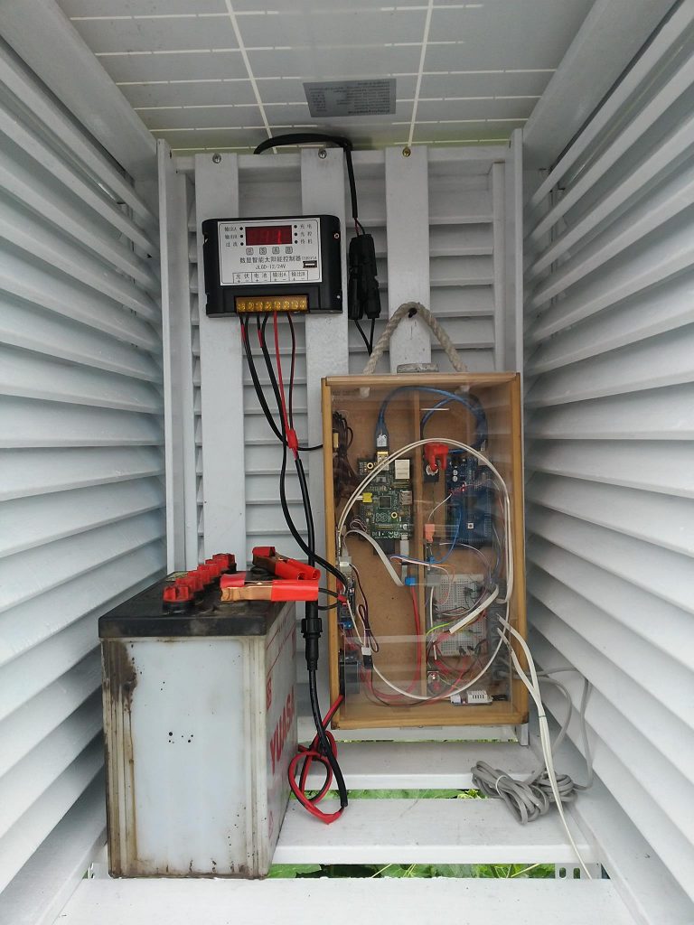
  • 百葉箱:百葉箱適合加上太陽能板、電瓶及網路,持續提供一定方圓公里內的氣候資訊。

lass.hackpad.com_c8meILUnsyi_p.525653_1464884983968_20160527_152733

13383974_10205084856880030_1294285006_o

機構零件

相關報導

科技農夫陳幸延──農田裡的開源自造者

RESOURCE

photo

空氣盒子

No Comments

空氣盒子背景介紹

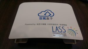
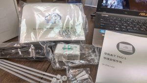
空氣盒子計劃是LASS核心概念的延伸,由華碩雲端、瑞昱半導體與中研院資訊所合作,發展一套簡易安裝的空氣品質監控設備,對於缺乏軟硬開發能力的人,提供一個監測PM2.5、溫度與濕度的管道,目前已提供300個空氣盒子給市民與學校,再將環境資訊上傳至雲端平台進行彙整,開放給研究機構分析汙染來源以及Makers進行創新加值應用,真正落實民眾參與、共同提升城市生活品質。

IMAG0021

a3

空氣盒子特色

  • 簡易安裝:簡單幾個步驟即可安裝完成,EdiGreen AirBox
  • 支援手機APP:用戶可以透過手機下載APP,即可在手機觀看即時空汙監測數據。
  • 視覺化的網頁數據顯示:空氣盒子

IMAG0017

規格

大小尺寸 148.4mm(W) x 111.5mm(H) x 45mm(D)
Wifi IEEE 802.11b/g/n
溫度感測範圍 0~60°C, Accuracy: ± 1 °C
濕度感測範圍 0~100%RH, Accuracy: ± 5% RH
PM2.5 量測範圍 minimum 0.3μm
PM2.5 計量效率 50%@0.3um, 98%@>=0.5 um
供電方式 Micro USB power port x 1 DC 5V
參考文件 快速安裝手冊 ,   FAQ

相關報導

Resource

lass.hackpad.com_32gq2eitJk5_p.461385_1446794878973_IMG_7674

LASS Field Try

No Comments

計劃緣起

LASS 團隊在建立許多測試硬體之後,發現為求更進一步發展,需要更大規模的實驗與更多的數據,才能達到真正對環境感測的測試與驗證,確認相關的系統設計的成熟度,因此發展出Field try可以讓廣大Maker可以加入環境感測的行列。


實踐方法

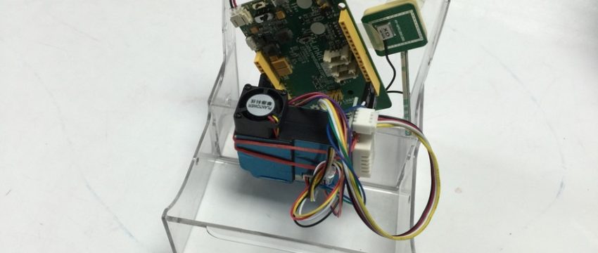
將配有PM2.5感測器與溫濕度感測器的Field try配置到各個環境,透過無限或是有線實體網路走MQTT protocol將sensor量測的數值上傳MQTT server,最後可依據不同方法如FTP或是存取ThingSpeak IOT cloud將資料連結到不同的applcation(如網頁:Realtime PM2.5 map)


計劃成果

1. Device ID: FT1_001

  lass.hackpad.com_32gq2eitJk5_p.461385_1446794879109_IMG_7675lass.hackpad.com_32gq2eitJk5_p.461385_1446794878973_IMG_7674

2. Device ID: FT1_005

lass.hackpad.com_32gq2eitJk5_p.494366_1448611811000_PB143195lass.hackpad.com_32gq2eitJk5_p.494366_1448611945017_PB143202

參加辦法


擷取

LASS Field Try 第二彈:即時數據呈現系統

No Comments

前情提要
  • 使用者需要一個即時知道自己感測器資料的方法,例如:
  1. FT1_001 的即時資料顯示介面(https://thingspeak.com/channels/61022
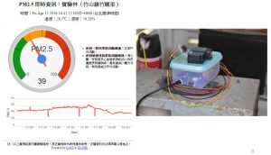
  1. FT1_001 的PM2.5 即時資訊儀表板介面(https://thingspeak.com/apps/plugins/25091
  • 以下介紹如何建立一個和上面例子中一樣的網頁
準備步驟
 Windows 作業系統
  • 要先確定電腦有安裝 python
  • WINDOWS 要注意環境變數要設定好
  • 開啟命令提示字元
  • 開始 –> 執行 –> cmd
  • 安裝 pip (Python套件管理程式ˇ)
  • 輸入 python get-pip.py
  • 利用 pip 來安裝 mqtt 函式庫
  • pip install paho-mqtt
  • pip install httplib2
  • 在 ThingSpeak.com 上建立一個帳號(若已有帳號可略過)
  • 使用ThingSpeak.com帳號登入系統後,選擇 Channels -> My Channels -> N
  • ew Channel
  • 在 New Channel 的設定網頁中依序填入
  • Name: 您所要呈現的 LASS Field Try 1 的設備 ID (FT1_XXX 格式)
  • Field 1: 輸入 PM2.5
  • Field 2: 先在旁邊方格打勾,接著在文字框輸入 Temperature
  • Field 3: 先在旁邊方格打勾,接著在文字框輸入 Humidity
  • Field 4: 先在旁邊方格打勾,接著在文字框輸入 Battery Level
  • Tags: 輸入 PM2.5, LASS, LinkIt One
  • Make Public?: 在方格打勾
  • 最後點擊 “Save Channel”
  • 在 My Channels 中選擇剛剛設定的 Channel,接著選取 API Keys,記下上面的 Write API Key (共16個英數字元)
  • 下載  lass_pm25_to_thingspeak.py
  • 執行 lass_pm25_to_thingspeak.py
  • 輸入 python lass_pm25_to_thingspeak.py FT1_0XX WRITE_ API_KEY
  • FT1_0XX 為裝置名稱
  • WRITE_ API_KEY 為寫入資料到 thinkspeak 所需要的 key
MAC 作業系統
  • 在 ThingSpeak.com 上建立一個帳號(若已有帳號可略過)
  • 使用ThingSpeak.com帳號登入系統後,選擇 Channels -> My Channels -> New Channel
  • 在 New Channel 的設定網頁中依序填入
  • Name: 您所要呈現的 LASS Field Try 1 的設備 ID (FT1_XXX 格式)
  • Field 1: 輸入 PM2.5
  • Field 2: 先在旁邊方格打勾,接著在文字框輸入 Temperature
  • Field 3: 先在旁邊方格打勾,接著在文字框輸入 Humidity
  • Field 4: 先在旁邊方格打勾,接著在文字框輸入 Battery Level
  • Tags: 輸入 PM2.5, LASS, LinkIt One
  • Make Public?: 在方格打勾
  • 最後點擊 “Save Channel”
  • 在 My Channels 中選擇剛剛設定的 Channel,接著選取 API Keys,記下上面的 Write API Key (共16個英數字元)
  • 執行LASS資料轉ThingSpeak程式:./lass_pm25_to_thingspeak.py LASS_DEVICE_ID ThingSpeak_API_Key
  • 其中 LASS_DEVICE_ID 為 LASS Field Try 1 的設備 ID (FT1_XXX 格式)
  • ThingSpeak_API_Key 為新設 ThingSpeak Channel的 ThingSpeak Channel (共16個英數字元)
  • 在unix like系統上,可用下列指令將程式丟到背景執行(除非關機,否則即使logout也會繼續執行): nohup ./lass_pm25_to_thingspeak.py LASS_DEVICE_ID ThingSpeak_API_Key &
  • python library installation
  • pip install paho-mqtt
  • pip install httplib2
  • 回到 ThingSpeak 網站,在 My Channels 中選擇剛剛設定的 Channel,接著選 Private View 或 Public View 即可見到即時更新的感測資料,其中 Public View 的網頁網址可以分享給其他朋友(不需要 ThingSpeak 帳號即可瀏覽)
其他功能
  • 若要自行撰寫資料相關程式,可參考 ThingSpeak API 網頁
  • 若要設定「斷線通知」,可在 ThingSpeak 下依照下列步驟設定
  • ThingSpeak 主畫面 -> Apps -> React
  • 點擊 「New React」
  • 在 React Name 輸入這個 Reack 的名稱,例如:”LASS FT1_XXX Offline”
  • 在 Condition Type 選擇 No Data Check
  • 在 Test Frequeny 選擇 Every 10 minutes
  • 在 Condition 的第一個選單中,選擇對應的 ThingSpeak Channel
  • 在 Condition 的第二個方框中,輸入 “2”
  • 在  Action 的選單中選擇 ThingTweek 
  • 在 then tweet 方框中輸入當設備斷線時,您希望收到的訊息,例如: “[LASS] Your device FT1_XXX is offline”
  • 在 using Twitter account 中,選取您的 Twitter 帳號 (註:您必須事先設定好 ThingSpeak 和您的 Twitter 帳號連結)
  • 在 Options 中選擇 Run action only the first time the condition is met
  • 點擊 「Save React」
  • 按照以上設定,倘若LASS設備出現當機現象時,最遲在 12 分鐘內,在您的 Twitter 帳號上便會收到 ThingSpeak 傳來的通知
  • 若要設定「PM2.5警報」,可在 ThingSpeak 下依照下列步驟設定
  • ThingSpeak 主畫面 -> Apps -> React
  • 點擊 「New React」
  • 在 React Name 輸入這個 Reack 的名稱,例如:”LASS FT1_XXX Alarm”
  • 在 Condition Type 選擇 Numeric
  • 在 Test Frequeny 選擇 Every 30 minutes
  • 在 Condition 的第一個選單中,選擇對應的 ThingSpeak Channel
  • 在 Condition 的第二個選單中,選擇 1 (PM2.5)
  • 在 Condition 的第三個選單中,選擇 is greather than
  • 在 Condition 的輸入方框中,輸入您想要設定的PM2.5警報臨界值,例如 35
  • 在  Action 的選單中選擇 ThingTweek 
  • 在 then tweet 方框中輸入當PM2.5超過臨界值時,您希望收到的訊息,例如: “[LASS] PM2.5 of FT1_XXX is %%trigger%% now!”,其中 %%trigger%% 將來在送出訊息時,會自動被取代成 PM2.5 的量測值
  • 在 using Twitter account 中,選取您的 Twitter 帳號 (註:您必須事先設定好 ThingSpeak 和您的 Twitter 帳號連結)
  • 在 Options 中選擇 Run action only the first time the condition is met
  • 點擊 「Save React」
  • 按照以上設定,倘若LASS設備量測到超過臨界值的 PM2.5濃度時,最遲在 30 分鐘內,在您的 Twitter 帳號上便會收到 ThingSpeak 傳來的通知
lass.hackpad1

LASS Field Try #1: Device Instructions(English)

No Comments

Hardware Instructions
  • Please prepare the following units
  • LinkIt One development board (including battery, GPS antenna, and WiFi antenna)
  • Note that the all-in-one package (including everything above) is available in the following links:
  • Linkit ONE HW block diagram:
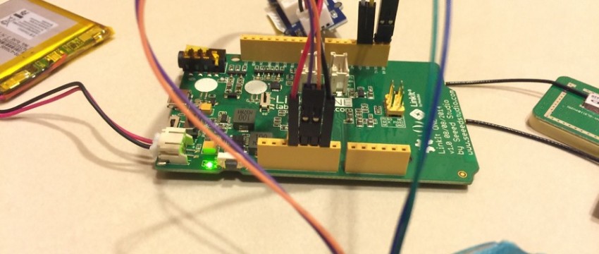
  • Please connect the battery, GPS receiver (the square one), and WiFi antenna (the thin rectangle one) to the LinkIt One board. You will find small text under the connectors noting GPS and WiFi on the board.
  • Please refit the 1st (purple), 2nd (orange), and 5th (green) wiring of the G3 sensor iknto the Dupont connector. (If you buy the all-in-one package from the above link, you can skip this step).
  • Please connect the following wirings of the G3 sensor to the corresponding pins on the LinkIt One board:
  • the 1st (purple) wiring to the 5V pin;
  • the 2nd (orange) wiring to the GND pin; and 
  • the 5th (green) wiring to the Rx pin.
  • Please connect the following wirings of the Grove – Temperature and Humidity Sensor Pro to the corresponding pins on the LinkIt One board:
  • the 1st (yellow) wiring to the D2 pin;
  • the 2nd (white) wiring to the D3 pin (this wiring is NOT used, and may have been removed in the all-in-one package provided in the above link); 
  • the 3rd (red) wiring to the 3V3 pin; and 
  • the 4th (black) wiring to the GND pin.
  • Now, the hardware is ready to work! Feel free to adjust the sensor and antenna to your favorite relative positions. You can also find a good cover/enclosure for your set. If you have a 3D printer, you may want to print out one of the existing design from the LASS archive (https://github.com/LinkItONEDevGroup/LASS/tree/master/3dp).
Software Instructions
  • If this your first time using LinkIt One, please refer to the official tutorial provided by MediaTek (MS Windows plafformMac OS platform). Note that, it is strongly recommend to use the Arduino IDE version indicated in the tutorial, otherwise you may experience a number of hardware related issues.
  • Please install the following libraries (from here) into your Arduino environment. In case you have trouble installing libraries into your Arduino environment, you may find this tutorial useful: Installing Additional Arduino Libraries.
  • Under Arduino IDE, please open the LASS.ino project, and edit the configuratin.h file as follows:
  • #define APP_ID (APPTYPE_SYSTEM_BASE+X): please change ‘X’ to ‘1’
  • #define DEVICE_ID “YOUR_DEVICE_NAME”: please change “YOUR_DEVICE_NAME” to your own device name. It is suggested to report your device name on the LASS page in order to prevent duplicate, which may result in issues in future data collection/analysis/visualization.
  • #define WIFI_SSID “LASS”: please change “LASS” to your WiFi SSID
  • #define WIFI_PASS “LASS123456”: please change “LASS123456” to your WiFi password (you can skip this step if there is no WiFi password)
  • #define WIFI_AUTH LWIFI_WPA: please keep it as it is (if you are using WPA encryption), or change it to “LWIFI_WEP” (if you are using WEP encryption) or “LWIFI_OPEN” (if there is no encryption used)
  • Now, the software is ready to go! Please compile the codes and upload to your LinkIt One board. (please make sure the board is connected to your PC).
Testing
  • You can also find the GIS visualization of your device at your location:
  • LASS also provides a number of approaches to access the measurement data of your device and other device. For more detailed information, please check out the webpage: LASS Data Platform
FAQ
  • Where can I find help if I need technical help?
  • You are welcome to post on LASS FB. Please do remember to include the error messages and other useful information so people in the community can help you.
  • You are also encouraged to help maintain this page, and make it more helpful for people in the LASS community.
1700_ahs4jmxb_w

室內環控系統 IASS(Indoor Aware Sensing System)

No Comments

專案介紹

雖說IASS也是一個LASS其中的專案,但不同的是IASS專注於室內環境感測,利用相同架構但不同的應用,LASS目標為量測整個大環境的數據,並將依照不同的地點的數據進行整合達到資料共享,而IASS則是收集某一室內的環境參數,監測室內是否合適人類居住或是室內是否存在危險性。

IASS分成三種版本,依據不同空間分類:

1.  辦公室專用感測裝置:一個好的工作效率需要良好的工作環境,因此此版本著重於量測二氧化碳與PM2.5濃度、溫溼度和光照,以提供良好工作環境的調整基準。

1700_ahs4jmxb_w

2.  居家安全專用感測裝置:雖說家裡是最舒適的環境,但往往因為過於舒適而忽略居住的安全性,而此版本則提供一氧化碳濃度與瓦斯天然氣濃度量測,提供居住的安全簡訊。

1812_l1gt5zrbew

3.  機房專用感測裝置:機房因為存放許多重要資料所以通常被公司視為非常重要的區域,這版本提供危害機房設備潛在因素的感測,像是漏水監測與可燃性氣體感測,提供公司安全維護的方法。

1796_z5fafaalpw

IASS特色

  • 任何人皆能DIY感測裝置:不需要程式設計或相關電子工程知識,每個人皆能DIY自己的環控系統。
  • 支援多種感測功能:目前支援12種環境感應功能:溫度,溼度,漏水,噪音,一氧化碳,天然氣, PM2.5, PM10, PM100, 二氧化碳,環境光照度,可依自身需求決定要加裝的感應器。
  • 不需要撰寫程式:提供現成的Arduino程式可直接使用,分為sensor與device兩種,使用者可依需求選擇不同的sensors程式搭配成device。
  • 提供預設搭配好的感測裝置:除了使用者可自行搭配決定感測器種類外,亦提供預設數種
  • 接上網路後會自動上傳ThingSpeak以提供遠端瀏覽觀看(需自行註冊ThingSpeak帳號並於程式中放入API KEY)
  • 支援上傳指定 server:除上傳ThingSpeak之外,亦可選擇將資料傳送到指定的server來接收。(使用GET)

相關資源

IASS github

未命名40

智慧家庭:PM2.5空氣感測器(電路設計下篇)

No Comments

作者:曹永忠/vMaker

本篇是接續上篇文章『智慧家庭:PM2.5空氣感測器(電路設計上篇)』,延續未完成的硬體電路組裝下篇,教大家如何組立空氣粒子感測裝置電子電路組裝。上文中我們介紹空氣粒子感測裝置的開發板安裝、空氣懸浮粒子感測器安裝,麵包板安裝、溫溼度模組安裝、RTC 時鐘模組安裝…等等,本篇將介紹空氣懸浮粒子感測器、LCD  2004 顯示模組等電路安裝,並進行第一階段的整合測試。

安裝 RTC 時鐘模組

我們加入 RTC 時鐘模組,如下圖所示進行電路連接。

未命名

(圖 1)安裝 RTC 時鐘模組

由於時間因素對本設計是一個非常重要的因素,由於阿米巴開發板並沒有內置時間模組,所以我們加入 RTC 時鐘模組。所以增加下表之接腳表,讓讀者更加了解。

(表 1)RTC 時鐘模組接腳表(累加接腳表)

未命名

我們將下表之 PMS 3003 空氣懸浮粒子感測器測試程式一攥寫好之後,編譯完成後上傳到 Ameba 開發板。

(表 2)PMS 3003 空氣懸浮粒子感測器測試程式一

PMS3003空氣懸浮粒子感測器測試程式一(PMS3003AirQualityV51A)
/*

This example demonstrate how to read pm2.5 value on PMS 3003 air condition sensor


PMS 3003 pin map is as follow:

PIN1  :VCC, connect to 5V

PIN2  :GND

PIN3  :SET, 0:Standby mode, 1:operating mode

PIN4  :RXD :Serial RX

PIN5  :TXD :Serial TX

PIN6  :RESET

PIN7  :NC

PIN8  :NC


In this example, we only use Serial to get PM 2.5 value.


The circuit:

* RX is digital pin 0 (connect to TX of PMS 3003)

* TX is digital pin 1 (connect to RX of PMS 3003)


*/

#define turnon HIGH

#define turnoff LOW

#include <WiFi.h>

#include “PMType.h”


#include <Wire.h>  // Arduino IDE 內建

// LCD I2C Library,從這裡可以下載:

// https://bitbucket.org/fmalpartida/new-liquidcrystal/downloads

#include <LiquidCrystal_I2C.h>


#include <SoftwareSerial.h>


#include “RTClib.h”

RTC_DS1307 RTC;

//DateTime nowT = RTC.now();


uint8_t MacData[6];


SoftwareSerial mySerial(0, 1); // RX, TX

IPAddress  Meip ,Megateway ,Mesubnet ;

String MacAddress ;

int status = WL_IDLE_STATUS;

boolean ParticleSensorStatus = true ;

#define pmsDataLen 32

uint8_t buf[pmsDataLen];

int idx = 0;

int pm25 = 0;

uint16_t PM01Value=0;          //define PM1.0 value of the air detector module

uint16_t PM2_5Value=0;         //define PM2.5 value of the air detector module

uint16_t PM10Value=0;         //define PM10 value of the air detector module

int NDPyear, NDPmonth, NDPday, NDPhour, NDPminute, NDPsecond;

LiquidCrystal_I2C lcd(0x27, 2, 1, 0, 4, 5, 6, 7, 3, POSITIVE);  // 設定 LCD I2C 位址


void setup() {

Serial.begin(9600);


mySerial.begin(9600); // PMS 3003 UART has baud rate 9600

lcd.begin(20, 4);      // 初始化 LCD,一行 20 的字元,共 4 行,預設開啟背光

lcd.backlight(); // 開啟背光

//  while(!Serial) ;

WiFi.status();    //this method must be used for get MAC

MacAddress = GetWifiMac() ;

ShowMac() ;

ShowDateTime() ;


}


void loop() { // run over and over

idx = 0;

memset(buf, 0, pmsDataLen);


while (mySerial.available())

{

buf[idx++] = mySerial.read();

}


// check if data header is correct

if (buf[0] == 0x42 && buf[1] == 0x4d)

{

pm25 = ( buf[12] << 8 ) | buf[13];

Serial.print(“pm2.5: “);

Serial.print(pm25);

Serial.println(” ug/m3″);

ShowPM(pm25) ;

}

}


void ShowMac()

{

lcd.setCursor(0, 0); // 設定游標位置在第一行行首

lcd.print(“MAC:”);

lcd.print(MacAddress);


}


void ShowDateTime()

{

lcd.setCursor(0, 2); // 設定游標位置在第一行行首

lcd.print(StrDate());

lcd.setCursor(11, 2); // 設定游標位置在第一行行首

lcd.print(StrTime());

//  lcd.print();


}


String  StrDate() {

String ttt ;

//nowT  = now;

DateTime now = RTC.now();

ttt = print4digits(now.year()) + “-” + print2digits(now.month()) + “-” + print2digits(now.day()) ;

//ttt = print4digits(NDPyear) + “/” + print2digits(NDPmonth) + “/” + print2digits(NDPday) ;

return ttt ;

}


String  StringDate(int yyy,int mmm,int ddd) {

String ttt ;

//nowT  = now;

ttt = print4digits(yyy) + “-” + print2digits(mmm) + “-” + print2digits(ddd) ;

return ttt ;

}


String  StrTime() {

String ttt ;

// nowT  = RTC.now();

DateTime now = RTC.now();

ttt = print2digits(now.hour()) + “:” + print2digits(now.minute()) + “:” + print2digits(now.second()) ;

//  ttt = print2digits(NDPhour) + “:” + print2digits(NDPminute) + “:” + print2digits(NDPsecond) ;

return ttt ;

}


String  StringTime(int hhh,int mmm,int sss) {

String ttt ;

ttt = print2digits(hhh) + “:” + print2digits(mmm) + “:” + print2digits(sss) ;

return ttt ;

}


String GetWifiMac()

{

String tt ;

String t1,t2,t3,t4,t5,t6 ;

WiFi.macAddress(MacData);


Serial.print(“Mac:”);

Serial.print(MacData[0],HEX) ;

Serial.print(“/”);

Serial.print(MacData[1],HEX) ;

Serial.print(“/”);

Serial.print(MacData[2],HEX) ;

Serial.print(“/”);

Serial.print(MacData[3],HEX) ;

Serial.print(“/”);

Serial.print(MacData[4],HEX) ;

Serial.print(“/”);

Serial.print(MacData[5],HEX) ;

Serial.print(“~”);


t1 = print2HEX((int)MacData[0]);

t2 = print2HEX((int)MacData[1]);

t3 = print2HEX((int)MacData[2]);

t4 = print2HEX((int)MacData[3]);

t5 = print2HEX((int)MacData[4]);

t6 = print2HEX((int)MacData[5]);

tt = (t1+t2+t3+t4+t5+t6) ;

Serial.print(tt);

Serial.print(“\n”);


return tt ;

}

String  print2HEX(int number) {

String ttt ;

if (number >= 0 && number < 16)

{

ttt = String(“0″) + String(number,HEX);

}

else

{

ttt = String(number,HEX);

}

return ttt ;

}

String  print2digits(int number) {

String ttt ;

if (number >= 0 && number < 10)

{

ttt = String(“0″) + String(number);

}

else

{

ttt = String(number);

}

return ttt ;

}


String  print4digits(int number) {

String ttt ;

ttt = String(number);

return ttt ;

}


void ShowPM(int pp25)

{

lcd.setCursor(0, 3); // 設定游標位置在第一行行首

lcd.print(”  PM2.5:     “);

lcd.setCursor(9, 3); // 設定游標位置在第一行行首

lcd.print(pp25);


}

資料下載:https://github.com/brucetsao/makerdiwo/tree/master/201604/PMS3003AirQualityV51A

由於,我們可以連上網際網路,也可以讀取時鐘模組,所以我們可以顯示網路資訊與時間資訊。我們將下表之 PMS 3003 空氣懸浮粒子感測器測試程式一攥寫好之後,編譯完成後上傳到 Ameba 開發板。

未命名

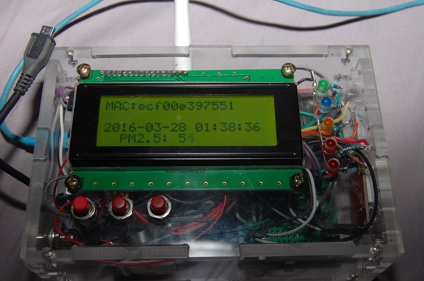
(圖 1)PMS 3003 空氣懸浮粒子感測器測試程式一畫面結果

擴充 RTC 時鐘模組網路校時能力

由於 RTC 時鐘模組是一個可以信賴的即時時鐘模組,但是如果新安裝裝置、更換電池或地區變更等等,都必須要將空氣粒子感測裝置帶回原開發者的研究室方可以更正於 RTC 時鐘模組的時間,雖然 Ameba 開發版有強大的無線網路連接網際網路的能力,但是在六秒中,除了重新讀取空氣粒子感測裝置的資料,還必須完成許多其他的工作,這些都必須耗費 Ameba 開發版的時間,與無線網路連接網際網路取得時間的成本,這樣對一個完善的空氣粒子感測裝置,太耗費在無線網路連接網際網路取得時間的成本。

所以我們如果能將系統修正,在每一次空氣粒子感測裝置開機後,即使用無線網路連接網際網路取得時間,並動態校正 RTC 時鐘模組,往後的時間就完全依靠內部的 RTC 時鐘模組運作,如此空氣粒子感測裝置可以更加完備,所以我們修改上述程式來達到此功能。

我們將下表之整合空氣懸浮粒子感測器測試程式二攥寫好之後,編譯完成後上傳到 Ameba 開發板。

(表 3)整合空氣懸浮粒子感測器測試程式二

整合空氣懸浮粒子感測器測試程式二(PMS3003AirQualityV71A)
/*

This example demonstrate how to read pm2.5 value on PMS 3003 air condition sensor


PMS 3003 pin map is as follow:

PIN1  :VCC, connect to 5V

PIN2  :GND

PIN3  :SET, 0:Standby mode, 1:operating mode

PIN4  :RXD :Serial RX

PIN5  :TXD :Serial TX

PIN6  :RESET

PIN7  :NC

PIN8  :NC


In this example, we only use Serial to get PM 2.5 value.


The circuit:

* RX is digital pin 0 (connect to TX of PMS 3003)

* TX is digital pin 1 (connect to RX of PMS 3003)


*/

#include <math.h>


#define turnon HIGH

#define turnoff LOW


#include “PMType.h”

#include <WiFi.h>

#include <WiFiUdp.h>

#include <Wire.h>  // Arduino IDE 內建

// LCD I2C Library,從這裡可以下載:

// https://bitbucket.org/fmalpartida/new-liquidcrystal/downloads


#include “RTClib.h”

RTC_DS1307 RTC;

//DateTime nowT = RTC.now();


#include <LiquidCrystal_I2C.h>

#include <SoftwareSerial.h>


uint8_t MacData[6];


SoftwareSerial mySerial(0, 1); // RX, TX

char ssid[] = “TSAO”;      // your network SSID (name)

char pass[] = “TSAO1234″;     // your network password

#define MAX_CLIENT_ID_LEN 10

#define MAX_TOPIC_LEN     50

char clientId[MAX_CLIENT_ID_LEN];

char outTopic[MAX_TOPIC_LEN];


IPAddress  Meip ,Megateway ,Mesubnet ;

String MacAddress ;

int status = WL_IDLE_STATUS;

boolean ParticleSensorStatus = true ;

WiFiUDP Udp;


const char ntpServer[] = “pool.ntp.org”;

const long timeZoneOffset = 28800L;

const int NTP_PACKET_SIZE = 48; // NTP time stamp is in the first 48 bytes of the message

const byte nptSendPacket[ NTP_PACKET_SIZE] = {

0xE3, 0x00, 0x06, 0xEC, 0x00, 0x00, 0x00, 0x00,  0x00, 0x00, 0x00, 0x00, 0x31, 0x4E, 0x31, 0x34,

0x00, 0x00, 0x00, 0x00, 0x00, 0x00, 0x00, 0x00,  0x00, 0x00, 0x00, 0x00, 0x00, 0x00, 0x00, 0x00,

0x00, 0x00, 0x00, 0x00, 0x00, 0x00, 0x00, 0x00,  0x00, 0x00, 0x00, 0x00, 0x00, 0x00, 0x00, 0x00

};

byte ntpRecvBuffer[ NTP_PACKET_SIZE ];


#define LEAP_YEAR(Y)     ( ((1970+Y)>0) && !((1970+Y)%4) && ( ((1970+Y)0) || !((1970+Y)%400) ) )

static  const uint8_t monthDays[]={31,28,31,30,31,30,31,31,30,31,30,31}; // API starts months from 1, this array starts from 0

uint32_t epochSystem = 0; // timestamp of system boot up


#define pmsDataLen 32

uint8_t buf[pmsDataLen];

int idx = 0;

int pm25 = 0;

uint16_t PM2_5Value=0;         //define PM2.5 value of the air detector module

int NDPyear, NDPmonth, NDPday, NDPhour, NDPminute, NDPsecond;

unsigned long epoch  ;

LiquidCrystal_I2C lcd(0x27, 2, 1, 0, 4, 5, 6, 7, 3, POSITIVE);  // 設定 LCD I2C 位址


void setup() {

Serial.begin(9600);

mySerial.begin(9600); // PMS 3003 UART has baud rate 9600

lcd.begin(20, 4);      // 初始化 LCD,一行 20 的字元,共 4 行,預設開啟背光

lcd.backlight(); // 開啟背光


MacAddress = GetWifiMac() ;

ShowMac() ;

initializeWiFi();


initRTC() ;

ShowDateTime() ;

delay(1500);

}


void loop() { // run over and over

ShowDateTime() ;

retrievePM25Value() ;

delay(1000); // delay 1 minute for next measurement


}


void ShowMac()

{

lcd.setCursor(0, 0); // 設定游標位置在第一行行首

lcd.print(“MAC:”);

lcd.print(MacAddress);


}


void ShowInternetStatus()

{

lcd.setCursor(0, 1); // 設定游標位置

if (WiFi.status())

{

Meip = WiFi.localIP();

lcd.print(“@:”);

lcd.print(Meip);


}

else

{

lcd.print(“DisConnected:”);


}


}

void ShowPM25(int pp25)

{

lcd.setCursor(0, 3); // 設定游標位置在第一行行首

lcd.print(“PM2.5:     “);

lcd.setCursor(9, 3); // 設定游標位置在第一行行首

lcd.print(pp25);


}


void ShowDateTime()

{

//  getCurrentTime(epoch, &NDPyear, &NDPmonth, &NDPday, &NDPhour, &NDPminute, &NDPsecond);

lcd.setCursor(0, 2); // 設定游標位置在第一行行首

lcd.print(StrDate());

lcd.setCursor(11, 2); // 設定游標位置在第一行行首

lcd.print(StrTime());

//  lcd.print();


}


String  StrDate() {

String ttt ;

//nowT  = now;

DateTime now = RTC.now();

ttt = print4digits(now.year()) + “-” + print2digits(now.month()) + “-” + print2digits(now.day()) ;

//ttt = print4digits(NDPyear) + “/” + print2digits(NDPmonth) + “/” + print2digits(NDPday) ;

return ttt ;

}


String  StringDate(int yyy,int mmm,int ddd) {

String ttt ;

//nowT  = now;

ttt = print4digits(yyy) + “-” + print2digits(mmm) + “-” + print2digits(ddd) ;

return ttt ;

}


String  StrTime() {

String ttt ;

// nowT  = RTC.now();

DateTime now = RTC.now();

ttt = print2digits(now.hour()) + “:” + print2digits(now.minute()) + “:” + print2digits(now.second()) ;

//  ttt = print2digits(NDPhour) + “:” + print2digits(NDPminute) + “:” + print2digits(NDPsecond) ;

return ttt ;

}


String  StringTime(int hhh,int mmm,int sss) {

String ttt ;

ttt = print2digits(hhh) + “:” + print2digits(mmm) + “:” + print2digits(sss) ;

return ttt ;

}


String GetWifiMac()

{

String tt ;

String t1,t2,t3,t4,t5,t6 ;

WiFi.status();    //this method must be used for get MAC

WiFi.macAddress(MacData);


Serial.print(“Mac:”);

Serial.print(MacData[0],HEX) ;

Serial.print(“/”);

Serial.print(MacData[1],HEX) ;

Serial.print(“/”);

Serial.print(MacData[2],HEX) ;

Serial.print(“/”);

Serial.print(MacData[3],HEX) ;

Serial.print(“/”);

Serial.print(MacData[4],HEX) ;

Serial.print(“/”);

Serial.print(MacData[5],HEX) ;

Serial.print(“~”);


t1 = print2HEX((int)MacData[0]);

t2 = print2HEX((int)MacData[1]);

t3 = print2HEX((int)MacData[2]);

t4 = print2HEX((int)MacData[3]);

t5 = print2HEX((int)MacData[4]);

t6 = print2HEX((int)MacData[5]);

tt = (t1+t2+t3+t4+t5+t6) ;

Serial.print(tt);

Serial.print(“\n”);


return tt ;

}

String  print2HEX(int number) {

String ttt ;

if (number >= 0 && number < 16)

{

ttt = String(“0″) + String(number,HEX);

}

else

{

ttt = String(number,HEX);

}

return ttt ;

}

String  print2digits(int number) {

String ttt ;

if (number >= 0 && number < 10)

{

ttt = String(“0″) + String(number);

}

else

{

ttt = String(number);

}

return ttt ;

}


String  print4digits(int number) {

String ttt ;

ttt = String(number);

return ttt ;

}


// send an NTP request to the time server at the given address

void retrieveNtpTime() {

Serial.println(“Send NTP packet”);


Udp.beginPacket(ntpServer, 123); //NTP requests are to port 123

Udp.write(nptSendPacket, NTP_PACKET_SIZE);

Udp.endPacket();


if(Udp.parsePacket()) {

Serial.println(“NTP packet received”);

Udp.read(ntpRecvBuffer, NTP_PACKET_SIZE); // read the packet into the buffer


unsigned long highWord = word(ntpRecvBuffer[40], ntpRecvBuffer[41]);

unsigned long lowWord = word(ntpRecvBuffer[42], ntpRecvBuffer[43]);

unsigned long secsSince1900 = highWord << 16 | lowWord;

const unsigned long seventyYears = 2208988800UL;

//     epoch = secsSince1900 – seventyYears + timeZoneOffset ;

epoch = secsSince1900 – seventyYears ;


epochSystem = epoch – millis() / 1000;

}

}


void getCurrentTime(unsigned long epoch, int *year, int *month, int *day, int *hour, int *minute, int *second) {

int tempDay = 0;


*hour = (epoch  % 86400L) / 3600;

*minute = (epoch  % 3600) / 60;

*second = epoch % 60;


*year = 1970;

*month = 0;

*day = epoch / 86400;


for (*year = 1970; ; (*year)++) {

if (tempDay + (LEAP_YEAR(*year) ? 366 : 365) > *day) {

break;

} else {

tempDay += (LEAP_YEAR(*year) ? 366 : 365);

}

}

tempDay = *day – tempDay; // the days left in a year

for ((*month) = 0; (*month) < 12; (*month)++) {

if ((*month) == 1) {

if (LEAP_YEAR(*year)) {

if (tempDay – 29 < 0) {

break;

} else {

tempDay -= 29;

}

} else {

if (tempDay – 28 < 0) {

break;

} else {

tempDay -= 28;

}

}

} else {

if (tempDay – monthDays[(*month)] < 0) {

break;

} else {

tempDay -= monthDays[(*month)];

}

}

}

(*month)++;

*day = tempDay+2; // one for base 1, one for current day

}


void retrievePM25Value() {

int idx;

bool hasPm25Value = false;

int timeout = 200;

while (!hasPm25Value) {

idx = 0;

memset(buf, 0, pmsDataLen);

while (mySerial.available()) {

buf[idx++] = mySerial.read();

}


if (buf[0] == 0x42 && buf[1] == 0x4d) {

pm25 = ( buf[12] << 8 ) | buf[13];

Serial.print(“pm2.5: “);

Serial.print(pm25);

Serial.print(” ug/m3″);

Serial.println(“”);

hasPm25Value = true;

ShowPM25(pm25) ;

}

timeout–;

if (timeout < 0) {

Serial.println(“fail to get pm2.5 data”);

break;

}

}

}


void initializeWiFi() {

while (status != WL_CONNECTED) {

Serial.print(“Attempting to connect to SSID: “);

Serial.println(ssid);

// Connect to WPA/WPA2 network. Change this line if using open or WEP network:

status = WiFi.begin(ssid, pass);

//   status = WiFi.begin(ssid);


// wait 10 seconds for connection:

delay(10000);

}


// local port to listen for UDP packets

Udp.begin(2390);

}


void printWifiData()

{

// print your WiFi shield’s IP address:

Meip = WiFi.localIP();

Serial.print(“IP Address: “);

Serial.println(Meip);


// print your MAC address:

byte mac[6];

WiFi.macAddress(mac);

Serial.print(“MAC address: “);

Serial.print(mac[5], HEX);

Serial.print(“:”);

Serial.print(mac[4], HEX);

Serial.print(“:”);

Serial.print(mac[3], HEX);

Serial.print(“:”);

Serial.print(mac[2], HEX);

Serial.print(“:”);

Serial.print(mac[1], HEX);

Serial.print(“:”);

Serial.println(mac[0], HEX);


// print your subnet mask:

Mesubnet = WiFi.subnetMask();

Serial.print(“NetMask: “);

Serial.println(Mesubnet);


// print your gateway address:

Megateway = WiFi.gatewayIP();

Serial.print(“Gateway: “);

Serial.println(Megateway);

}


void initRTC()

{

Wire.begin();

RTC.begin();

SetRTCFromNtpTime() ;

if (! RTC.isrunning()) {

Serial.println(“RTC is NOT running!”);

// following line sets the RTC to the date & time this sketch was compiled

//    RTC.adjust(DateTime(__DATE__, __TIME__));


}

}

void SetRTCFromNtpTime()

{

retrieveNtpTime();

//DateTime ttt;

getCurrentTime(epoch+timeZoneOffset, &NDPyear, &NDPmonth, &NDPday, &NDPhour, &NDPminute, &NDPsecond);

//ttt->year = NDPyear ;

Serial.print(“NDP Date is :”);

Serial.print(StringDate(NDPyear,NDPmonth,NDPday));

Serial.print(“and “);

Serial.print(“NDP Time is :”);

Serial.print(StringTime(NDPhour,NDPminute,NDPsecond));

Serial.print(“\n”);


RTC.adjust(DateTime(epoch+timeZoneOffset));


}

資料下載:https://github.com/brucetsao/makerdiwo/tree/master/201604/ PMS3003AirQualityV71A

由於空氣粒子感測裝置每次開機時,我們可以連上網際網路,使用無線網路連接網際網路取得時間,並動態校正 RTC 時鐘模組,往後的時間就完全依靠內部的 RTC 時鐘模組運作。

未命名

(圖 2-a)開發 IDE 監控畫面

未命名

(圖 2-b)校時之後空氣粒子感測裝置 LCD 顯示畫面

擴充溫溼度感測器

由於完整的空氣粒子感測裝置除了偵測空氣中懸浮微粒的濃度,基本的溫溼度資訊也是必需的需求,所以我們加入溫溼度感測器模組。

未命名

(圖 2)安裝溫溼度感測器

請讀者依照下表之接腳表,進行電路組立。

(表 4)溫溼度感測器接腳表(累加接腳表)

未命名

我們將下表之整合空氣懸浮粒子感測器測試程式三攥寫好之後,編譯完成後上傳到 Ameba 開發板。

(表 5)整合空氣懸浮粒子感測器測試程式三

整合空氣懸浮粒子感測器測試程式三(PMS3003AirQualityV81A)
/*

This example demonstrate how to read pm2.5 value on PMS 3003 air condition sensor


PMS 3003 pin map is as follow:

PIN1  :VCC, connect to 5V

PIN2  :GND

PIN3  :SET, 0:Standby mode, 1:operating mode

PIN4  :RXD :Serial RX

PIN5  :TXD :Serial TX

PIN6  :RESET

PIN7  :NC

PIN8  :NC


In this example, we only use Serial to get PM 2.5 value.


The circuit:

* RX is digital pin 0 (connect to TX of PMS 3003)

* TX is digital pin 1 (connect to RX of PMS 3003)


*/

#include <math.h>


#define turnon HIGH

#define turnoff LOW

#define DHTSensorPin 7


#include “PMType.h”

#include <WiFi.h>

#include <WiFiUdp.h>

#include <Wire.h>  // Arduino IDE 內建

// LCD I2C Library,從這裡可以下載:

// https://bitbucket.org/fmalpartida/new-liquidcrystal/downloads


#include “RTClib.h”

RTC_DS1307 RTC;

//DateTime nowT = RTC.now();

#include “DHT.h”

// Uncomment whatever type you’re using!

//#define DHTTYPE DHT11   // DHT 11

#define DHTTYPE DHT22   // DHT 22  (AM2302), AM2321

//#define DHTTYPE DHT21   // DHT 21 (AM2301)


#include <LiquidCrystal_I2C.h>

#include <SoftwareSerial.h>


uint8_t MacData[6];


SoftwareSerial mySerial(0, 1); // RX, TX

char ssid[] = “TSAO”;      // your network SSID (name)

char pass[] = “TSAO1234″;     // your network password

#define MAX_CLIENT_ID_LEN 10

#define MAX_TOPIC_LEN     50

char clientId[MAX_CLIENT_ID_LEN];

char outTopic[MAX_TOPIC_LEN];


IPAddress  Meip ,Megateway ,Mesubnet ;

String MacAddress ;

int status = WL_IDLE_STATUS;

boolean ParticleSensorStatus = true ;

WiFiUDP Udp;


const char ntpServer[] = “pool.ntp.org”;

const long timeZoneOffset = 28800L;

const int NTP_PACKET_SIZE = 48; // NTP time stamp is in the first 48 bytes of the message

const byte nptSendPacket[ NTP_PACKET_SIZE] = {

0xE3, 0x00, 0x06, 0xEC, 0x00, 0x00, 0x00, 0x00,  0x00, 0x00, 0x00, 0x00, 0x31, 0x4E, 0x31, 0x34,

0x00, 0x00, 0x00, 0x00, 0x00, 0x00, 0x00, 0x00,  0x00, 0x00, 0x00, 0x00, 0x00, 0x00, 0x00, 0x00,

0x00, 0x00, 0x00, 0x00, 0x00, 0x00, 0x00, 0x00,  0x00, 0x00, 0x00, 0x00, 0x00, 0x00, 0x00, 0x00

};

byte ntpRecvBuffer[ NTP_PACKET_SIZE ];


#define LEAP_YEAR(Y)     ( ((1970+Y)>0) && !((1970+Y)%4) && ( ((1970+Y)0) || !((1970+Y)%400) ) )

static  const uint8_t monthDays[]={31,28,31,30,31,30,31,31,30,31,30,31}; // API starts months from 1, this array starts from 0

uint32_t epochSystem = 0; // timestamp of system boot up


#define pmsDataLen 32

uint8_t buf[pmsDataLen];

int idx = 0;

int pm25 = 0;

uint16_t PM2_5Value=0;         //define PM2.5 value of the air detector module

int NDPyear, NDPmonth, NDPday, NDPhour, NDPminute, NDPsecond;

unsigned long epoch  ;

int HumidityData = 0 ;

int TemperatureData = 0 ;


LiquidCrystal_I2C lcd(0x27, 2, 1, 0, 4, 5, 6, 7, 3, POSITIVE);  // 設定 LCD I2C 位址

DHT dht(DHTSensorPin, DHTTYPE);


void setup() {

Serial.begin(9600);

mySerial.begin(9600); // PMS 3003 UART has baud rate 9600

lcd.begin(20, 4);      // 初始化 LCD,一行 20 的字元,共 4 行,預設開啟背光

lcd.backlight(); // 開啟背光


MacAddress = GetWifiMac() ;

ShowMac() ;

initializeWiFi();


initRTC() ;

ShowDateTime() ;

ShowInternetStatus() ;

delay(1500);

}


void loop() { // run over and over

ShowDateTime() ;

retrievePM25Value() ;

ShowHumidity() ;

delay(1000); // delay 1 minute for next measurement


}


void ShowMac()

{

lcd.setCursor(0, 0); // 設定游標位置在第一行行首

lcd.print(“MAC:”);

lcd.print(MacAddress);


}


void ShowInternetStatus()

{

lcd.setCursor(0, 1); // 設定游標位置

if (WiFi.status())

{

Meip = WiFi.localIP();

lcd.print(“@:”);

lcd.print(Meip);


}

else

{

lcd.print(“DisConnected:”);


}


}

void ShowPM25(int pp25)

{

lcd.setCursor(0, 3); // 設定游標位置在第一行行首

lcd.print(“PM2.5:     “);

lcd.setCursor(9, 3); // 設定游標位置在第一行行首

lcd.print(pp25);


}


void ShowDateTime()

{

//  getCurrentTime(epoch, &NDPyear, &NDPmonth, &NDPday, &NDPhour, &NDPminute, &NDPsecond);

lcd.setCursor(0, 2); // 設定游標位置在第一行行首

lcd.print(StrDate());

lcd.setCursor(11, 2); // 設定游標位置在第一行行首

lcd.print(StrTime());

//  lcd.print();


}


String  StrDate() {

String ttt ;

//nowT  = now;

DateTime now = RTC.now();

ttt = print4digits(now.year()) + “-” + print2digits(now.month()) + “-” + print2digits(now.day()) ;

//ttt = print4digits(NDPyear) + “/” + print2digits(NDPmonth) + “/” + print2digits(NDPday) ;

return ttt ;

}


String  StringDate(int yyy,int mmm,int ddd) {

String ttt ;

//nowT  = now;

ttt = print4digits(yyy) + “-” + print2digits(mmm) + “-” + print2digits(ddd) ;

return ttt ;

}


String  StrTime() {

String ttt ;

// nowT  = RTC.now();

DateTime now = RTC.now();

ttt = print2digits(now.hour()) + “:” + print2digits(now.minute()) + “:” + print2digits(now.second()) ;

//  ttt = print2digits(NDPhour) + “:” + print2digits(NDPminute) + “:” + print2digits(NDPsecond) ;

return ttt ;

}


String  StringTime(int hhh,int mmm,int sss) {

String ttt ;

ttt = print2digits(hhh) + “:” + print2digits(mmm) + “:” + print2digits(sss) ;

return ttt ;

}


String GetWifiMac()

{

String tt ;

String t1,t2,t3,t4,t5,t6 ;

WiFi.status();    //this method must be used for get MAC

WiFi.macAddress(MacData);


Serial.print(“Mac:”);

Serial.print(MacData[0],HEX) ;

Serial.print(“/”);

Serial.print(MacData[1],HEX) ;

Serial.print(“/”);

Serial.print(MacData[2],HEX) ;

Serial.print(“/”);

Serial.print(MacData[3],HEX) ;

Serial.print(“/”);

Serial.print(MacData[4],HEX) ;

Serial.print(“/”);

Serial.print(MacData[5],HEX) ;

Serial.print(“~”);


t1 = print2HEX((int)MacData[0]);

t2 = print2HEX((int)MacData[1]);

t3 = print2HEX((int)MacData[2]);

t4 = print2HEX((int)MacData[3]);

t5 = print2HEX((int)MacData[4]);

t6 = print2HEX((int)MacData[5]);

tt = (t1+t2+t3+t4+t5+t6) ;

Serial.print(tt);

Serial.print(“\n”);


return tt ;

}

String  print2HEX(int number) {

String ttt ;

if (number >= 0 && number < 16)

{

ttt = String(“0″) + String(number,HEX);

}

else

{

ttt = String(number,HEX);

}

return ttt ;

}

String  print2digits(int number) {

String ttt ;

if (number >= 0 && number < 10)

{

ttt = String(“0″) + String(number);

}

else

{

ttt = String(number);

}

return ttt ;

}


String  print4digits(int number) {

String ttt ;

ttt = String(number);

return ttt ;

}


// send an NTP request to the time server at the given address

void retrieveNtpTime() {

Serial.println(“Send NTP packet”);


Udp.beginPacket(ntpServer, 123); //NTP requests are to port 123

Udp.write(nptSendPacket, NTP_PACKET_SIZE);

Udp.endPacket();


if(Udp.parsePacket()) {

Serial.println(“NTP packet received”);

Udp.read(ntpRecvBuffer, NTP_PACKET_SIZE); // read the packet into the buffer


unsigned long highWord = word(ntpRecvBuffer[40], ntpRecvBuffer[41]);

unsigned long lowWord = word(ntpRecvBuffer[42], ntpRecvBuffer[43]);

unsigned long secsSince1900 = highWord << 16 | lowWord;

const unsigned long seventyYears = 2208988800UL;

//     epoch = secsSince1900 – seventyYears + timeZoneOffset ;

epoch = secsSince1900 – seventyYears ;


epochSystem = epoch – millis() / 1000;

}

}


void getCurrentTime(unsigned long epoch, int *year, int *month, int *day, int *hour, int *minute, int *second) {

int tempDay = 0;


*hour = (epoch  % 86400L) / 3600;

*minute = (epoch  % 3600) / 60;

*second = epoch % 60;


*year = 1970;

*month = 0;

*day = epoch / 86400;


for (*year = 1970; ; (*year)++) {

if (tempDay + (LEAP_YEAR(*year) ? 366 : 365) > *day) {

break;

} else {

tempDay += (LEAP_YEAR(*year) ? 366 : 365);

}

}

tempDay = *day – tempDay; // the days left in a year

for ((*month) = 0; (*month) < 12; (*month)++) {

if ((*month) == 1) {

if (LEAP_YEAR(*year)) {

if (tempDay – 29 < 0) {

break;

} else {

tempDay -= 29;

}

} else {

if (tempDay – 28 < 0) {

break;

} else {

tempDay -= 28;

}

}

} else {

if (tempDay – monthDays[(*month)] < 0) {

break;

} else {

tempDay -= monthDays[(*month)];

}

}

}

(*month)++;

*day = tempDay+2; // one for base 1, one for current day

}


void retrievePM25Value() {

int idx;

bool hasPm25Value = false;

int timeout = 200;

while (!hasPm25Value) {

idx = 0;

memset(buf, 0, pmsDataLen);

while (mySerial.available()) {

buf[idx++] = mySerial.read();

}


if (buf[0] == 0x42 && buf[1] == 0x4d) {

pm25 = ( buf[12] << 8 ) | buf[13];

Serial.print(“pm2.5: “);

Serial.print(pm25);

Serial.print(” ug/m3″);

Serial.println(“”);

hasPm25Value = true;

ShowPM25(pm25) ;

}

timeout–;

if (timeout < 0) {

Serial.println(“fail to get pm2.5 data”);

break;

}

}

}


void initializeWiFi() {

while (status != WL_CONNECTED) {

Serial.print(“Attempting to connect to SSID: “);

Serial.println(ssid);

// Connect to WPA/WPA2 network. Change this line if using open or WEP network:

status = WiFi.begin(ssid, pass);

//   status = WiFi.begin(ssid);


// wait 10 seconds for connection:

delay(10000);

}


// local port to listen for UDP packets

Udp.begin(2390);

}


void printWifiData()

{

// print your WiFi shield’s IP address:

Meip = WiFi.localIP();

Serial.print(“IP Address: “);

Serial.println(Meip);


// print your MAC address:

byte mac[6];

WiFi.macAddress(mac);

Serial.print(“MAC address: “);

Serial.print(mac[5], HEX);

Serial.print(“:”);

Serial.print(mac[4], HEX);

Serial.print(“:”);

Serial.print(mac[3], HEX);

Serial.print(“:”);

Serial.print(mac[2], HEX);

Serial.print(“:”);

Serial.print(mac[1], HEX);

Serial.print(“:”);

Serial.println(mac[0], HEX);


// print your subnet mask:

Mesubnet = WiFi.subnetMask();

Serial.print(“NetMask: “);

Serial.println(Mesubnet);


// print your gateway address:

Megateway = WiFi.gatewayIP();

Serial.print(“Gateway: “);

Serial.println(Megateway);

}


void initRTC()

{

Wire.begin();

RTC.begin();

SetRTCFromNtpTime() ;

if (! RTC.isrunning()) {

Serial.println(“RTC is NOT running!”);

// following line sets the RTC to the date & time this sketch was compiled

//    RTC.adjust(DateTime(__DATE__, __TIME__));


}

}

void SetRTCFromNtpTime()

{

retrieveNtpTime();

//DateTime ttt;

getCurrentTime(epoch+timeZoneOffset, &NDPyear, &NDPmonth, &NDPday, &NDPhour, &NDPminute, &NDPsecond);

//ttt->year = NDPyear ;

Serial.print(“NDP Date is :”);

Serial.print(StringDate(NDPyear,NDPmonth,NDPday));

Serial.print(“and “);

Serial.print(“NDP Time is :”);

Serial.print(StringTime(NDPhour,NDPminute,NDPsecond));

Serial.print(“\n”);


RTC.adjust(DateTime(epoch+timeZoneOffset));


}

void ShowHumidity()

{

float h = dht.readHumidity();

// Read temperature as Celsius (the default)

float t = dht.readTemperature();

// Read temperature as Fahrenheit (isFahrenheit = true)

float f = dht.readTemperature(true);

HumidityData = (int)h ;

TemperatureData = (int)t ;

Serial.print(“Humidity :”) ;

Serial.print(h) ;

Serial.print(“%  /”) ;

Serial.print(t) ;

Serial.print(“C  \n”) ;

// Check if any reads failed and exit early (to try again).

if (isnan(h) || isnan(t) || isnan(f)) {

Serial.println(“Failed to read from DHT sensor!”);

return;

}

lcd.setCursor(11, 3); // 設定游標位置在第一行行首

lcd.print((int)h);

lcd.print(“% “);

lcd.print((int)t);


}


資料下載:https://github.com/brucetsao/makerdiwo/tree/master/201604/ PMS3003AirQualityV81A

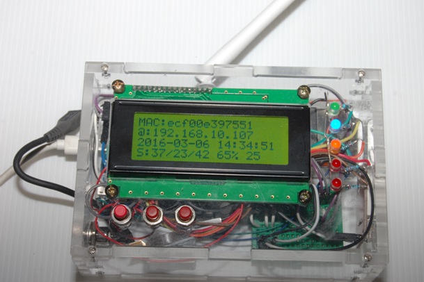
我們可以連上網際網路,也可以偵測 PM 2.5 的空氣懸浮粒子、PM 1.0 的空氣懸浮粒子 &  PM 10 的空氣懸浮粒子,溫度、濕度都也可以偵測到值。

未命名

(圖 3-a)讀取完整溫溼度等資料之開發 IDE 監控畫面

未命名

(圖 3-b)空氣粒子感測裝置完整資訊之 LCD 顯示畫面

本文為『PM2.5空氣感測器』系列第四篇:電路設計下篇,主要介紹如何將 PM 2.5 空氣感測器加入 RTC 時鐘模組,溫溼度感測模組,並將『PM2.5空氣感測器』系列第三篇:電路設計上篇與本篇文章一同閱讀與整合,逐一完成 PM 2.5 空氣感測器的電路安裝。

後續筆者還會繼續發表『PM2.5空氣感測器』系列的文章,讓我們在未來可以創造出更優質、智慧化的家庭。

參考資料:


post_56e916a97b250

智慧家庭:PM2.5 空氣感測器(硬體組裝上篇)

No Comments

作者:曹永忠/vMaker

本篇主要是教大家如何組立空氣粒子感測裝置硬體組裝,但是為了讓讀者簡化實驗,並不讓讀者自行設計與製作空氣粒子感測裝置外部產品硬體結構,而是採用市面上各個相關模組來設計出空氣粒子感測裝置。

空氣粒子感測裝置基本組成要素

首先,我們先將購買所需的元件,由下圖可以見到以下所有零件的一覽圖:

未命名

未命名

未命名

本文所有的零件都會以零件包的方式出版,並跟國內最大的電子零件供應商 iCShop 合作,讀者若有任何需要,請逕行與該公司接洽。對於零件使用上,若讀者仍不熟悉,可以參考文末的參考資料。

安裝阿米巴開發板

首先,我們先行安裝瑞昱半導體公司的阿米巴(Ameba)開發板(圖(b)),如下圖所示,我們先拿出外殼(圖(z))的四顆塑膠螺絲柱與四顆塑膠螺絲。

未命名

(圖 2)阿米巴開發板固定柱

如下圖所示,我們先拿出外殼底板,並將上圖所示之的四顆塑膠支柱與四顆塑膠螺絲,鎖於如下圖所示之底板上。

未命名

(圖 3)將固定柱鎖於外殼底板

將瑞昱半導體公司的阿米巴(Ameba)開發板置於上圖所示之的塑膠支柱上,並拿出與四顆塑膠螺絲帽,將之固定鎖緊。

未命名

(圖 4)將阿米巴開發板鎖於外殼底板

如上圖所示,我們完成出瑞昱半導體公司的阿米巴(Ameba)開發板之裝設。

安裝偵測空氣懸浮粒子感測器

下一步我們將裝設明攀藤科技(Plantower)的 PMS3003 空氣懸浮粒子感測器(註 1),首先我們拿出外殼元件內的小螺絲與小螺絲帽,如下圖所示,先放於桌面上。

未命名

(圖 5)固定 PM 感測器之螺絲

如下圖所示,我們拿出如圖(a)所示之偵測空氣懸浮粒子感測器(PMS3003),並且先將塑膠膜拆開,可以看到如下圖所示之對稱的兩個螺絲孔。

未命名

(圖 6)空氣懸浮粒子感測器

如下圖所示,我們將如上圖所示之對稱的兩個螺絲孔,對齊外殼底板之右上方兩個螺孔,位置如下圖所示之位置。

未命名

(圖 7)安裝空氣懸浮粒子感測器於底板上

如下圖所示,我們將螺絲由外殼底板之右上方兩個螺孔往上插入後,如下圖所示,將螺絲帽旋緊。

未命名

(圖 8)鎖緊空氣懸浮粒子感測器螺絲

完成裝置偵測空氣懸浮粒子感測器(PMS3003)之後,整個外觀如下圖所示。

未命名

(圖 9)空氣懸浮粒子感測器安裝完成

安裝麵包板

下一步我們將裝設小型麵包板(圖(f)),因為我們必須裝設許多元件,如果所有元件都直接連接到阿米巴開發板,恐怕無法同時間連接這麼多必要的元件,所以我們必須透過麵包板來擴充可以連接的元件,特別是每一個元件都需要電力供應,而阿米巴開發板無法同時供應這麼多的元件電源插孔。

未命名

(圖 10)麵包板

為了擴充麵包板,我們先拿出單心線(圖(g)),如下圖所示,先將單心線進行裁剪。

未命名

(圖 11)單心線

如下圖所示,我們先把上圖所示之單心線,進行裁剪單心線為五條 45 mm~55 mm 長度,並使用撥線鉗或斜口鉗將五條單心線雙邊各剝去 6 mm~8 mm 長度的外皮,使之露出金屬的單心銅線。

未命名

(圖 12)五條單心線

將五條剝去外皮單心線依序插入下圖所示之麵包板,使之橫跨五個雙邊通道,使之導通。

未命名

(圖 13)裝置單心線於麵包板

如下圖所示,我們再剪單心線一條 25 mm~35 mm 長度,並使用撥線鉗或斜口鉗將一條單心線雙邊各剝去 6 mm~8 mm 長度的外皮,使之露出金屬的單心銅線。

未命名

(圖 14)補上單心線

如下圖所示,將一條剝去外皮單心線依序插入麵包板,使之連接第二條與第三條單心線的通道,使之導通。

未命名

(圖 15)連接 VCC 雙線

最後,我們將完成單心線布置的麵包板放置外殼底板之右下方,整個外觀如下圖所示。

未命名

(圖 16)安裝麵包板於底殼上

安裝溫溼度模組

因為我們需要量測溫度、濕度,如果使用單一功能的感測器,會增加裝置元件,所以我們採用溫溼度合一感測元件:DHT22溫濕度模組(圖(e))。

首先,我們將外殼之右側板如下圖所示放置。

未命名

(圖 17)外殼右側

如下圖所示,我們取出一個小螺絲與小螺帽以及 DHT22 溫濕度模組。

未命名

(圖 18)DHT22 與螺絲

由於外殼設計因素,我們將 DHT22 溫濕度模組的接腳解焊,重新焊接一個 180 度的三 pin 的接腳。

未命名

(圖 19)改裝腳位的 DHT22

將 DHT22 溫濕度模組塞入右側板的下方,並將 DHT22 溫濕度模組上方孔洞,對準右側板的孔洞,方便鎖螺絲。

未命名

(圖 20)將 DHT22 裝於外殼上

如下圖所示,將 DHT22 溫濕度模組於右側板的孔洞,將螺絲鎖入後,用螺帽旋緊。

未命名

(圖 21)將 DHT22 鎖緊於外殼上

取出三條一公一母杜邦線(圖(h)),準備連接 DHT22 溫濕度模組。

未命名

(圖 22)取出 DHT22 的杜邦線

三條一公一母杜邦線,連接於 DHT22 溫濕度模組之電源接腳與訊號接腳。

未命名

(圖 23)將杜邦線插於 DHT22 上

完成將 DHT22 溫濕度模組置於外殼右板上。

安裝 RTC 時鐘模組

由於本裝置需要精準的時間與持續不斷的時間資訊,如果耗用阿米巴開發板於計算時間會大材小用,而且可能增加程式的複雜度。所以我們引入了時鐘模組,採用 Tiny RTC DS1307 時鐘模組(圖(d))。

首先,我們將外殼的下側板如下圖所示放置。

未命名

(圖 24)外殼下板

如下圖所示,我們取出一個 DS1307 RTC 時鐘模組,再取出如泡棉膠(圖(m))。

未命名

(圖 25)取出 RTC 時鐘模組

我們將泡棉膠撕開一面,黏到 DS1307 RTC 時鐘模組上。

未命名

(圖 26)黏上雙面膠於 RTC 時鐘模組

我們再將泡棉膠另一面撕開,黏到外殼的中間偏左方的位置上。

未命名

(圖 27)將 RTC 時鐘模組黏到外殼

如下圖所示,我們取出四條一公一母杜邦線,準備連接 DS1307 RTC 時鐘模組。

未命名

(圖 28)取出 RTC 用的杜邦線

我們將四條一公一母杜邦線,連接於 DS1307 RTC 時鐘模組之電源接腳與 I2C 訊號接腳。

未命名

(圖 29)將杜邦線裝於 RTC 時鐘模組

預期完成組裝目標

當完成硬體、電路與軟體安裝後,只要再接上電源就可以完成 PM2.5 空氣感測器的裝置了。

未命名

(圖 59)正常開機之成品圖

本文為『PM 2.5 空氣感測器』系列第二篇:硬體組裝篇上,主要介紹之裝置所有元件,並且一步一步教導讀者如何將這些元件組裝,完成 PM 2.5 空氣感測器的硬體安裝。後續筆者還會繼續發表『PM 2.5 空氣感測器』系列的文章,讓我們在未來可以創造出更優質、智慧化的家庭。

註 1:北京攀藤科技有限公司是一家專注於空氣品質感測器研發、生產與銷售的高科技企業,作為行業領跑者,公司通過不斷創新和品質追求,已與國內外多家知名企業建立了良好的戰略合作夥伴關係。

參考資料:

  • 曹永忠. (2016). 智慧家庭:PM2.5 空氣感測器(感測器篇).   Retrieved fromhttp://vmaker.tw/project/view/695
  • 曹永忠, 许智诚, & 蔡英德. (2014). Arduino 电风扇设计与制作: Using Arduino to Develop a Controller of the Electric Fan. 台湾、彰化: 渥玛数位有限公司.
  • 曹永忠, 許智誠, & 蔡英德. (2013). Arduino 電風扇設計與製作: The Design and Development of an Electronic Fan by Arduino Technology (初版 ed.). 台灣、彰化: 渥瑪數位有限公司.
  • 曹永忠, 許智誠, & 蔡英德. (2014a). Arduino EM-RFID 門禁管制機設計:The Design of an Entry Access Control Device based on EM-RFID Card (初版 ed.). 台灣、彰化: 渥瑪數位有限公司.
  • 曹永忠, 許智誠, & 蔡英德. (2014b). Arduino RFID 门禁管制机设计: Using Arduino to Develop an Entry Access Control Device with RFID Tags. 台湾、彰化: 渥瑪數位有限公司.
  • 曹永忠, 許智誠, & 蔡英德. (2014c). Arduino RFID 門禁管制機設計: The Design of an Entry Access Control Device based on RFID Technology (初版 ed.). 台灣、彰化: 渥瑪數位有限公司.
  • 曹永忠, 許智誠, & 蔡英德. (2015a). Ameba 空气粒子感测装置设计与开发(MQTT篇):Using Ameba to Develop a PM 2.5 Monitoring Device to MQTT (初版 ed.). 台湾、彰化: 渥瑪數位有限公司.
  • 曹永忠, 許智誠, & 蔡英德. (2015b). Ameba 空氣粒子感測裝置設計與開發(MQTT篇)):Using Ameba to Develop a PM 2.5 Monitoring Device to MQTT (初版 ed.). 台湾、彰化: 渥瑪數位有限公司.
c21b0febfc644717851f4fd0b6286e6b

LASS4U 專案

No Comments

專案背景

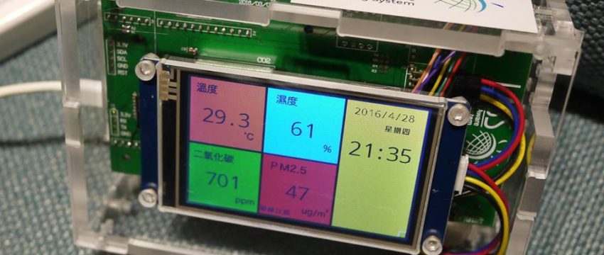
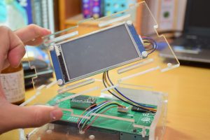
LASS硬體發展從一開始的FieldTry到空氣盒子,可以了解到硬體的規格與完整度的提升,而LASS4U則是繼承前面兩者的優點繼續法展下去,並且加入觸控螢幕讓使用者在不用開啟網頁或是手機app,便可得知即時資訊,此外有鑑於近年來溫室效應加劇,其中又以二氧化碳更是影響巨大,因此LASS社群出現了加入二氧化碳感測的想法。


LASS4U功能與特色

  • 公益開源專案
  • 可感測 CO2, Temperature, Humidity, PM2.5, (PM1, PM10)
  • 完支援 LASS 感測器網路架構
  • 全彩螢幕顯示目前感測值與歷史圖表
  • 與周圍 LASS 感測站,歷史感測值比較
  • 開放支援雲端運算與資料分析,更容易做加值應用


DSC_1239

DSC_1246

DSC_1248

硬體資料

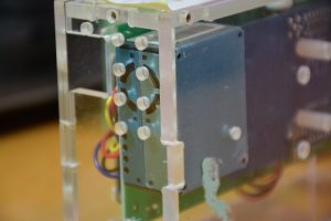
開發版:REALTEK AMEBA

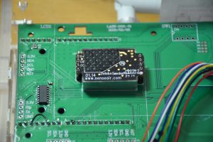
LASS4U Module:感測元件 – PMS3003(G3)/SenseAir S8 CO2/Sensiron SHT31 溫濕度)


LASS4U公益贊助名單

物聯網晶片:瑞昱半導體

製造服務:邁特電子

雲端運算:Ling-Jyh Chen

硬體設計:Seng Yong Lan

通路服務:iCShopping

媒體協力:MakerPro

軟體開發:肉多多植物科技農場 – 阿海(MingWei Cheng)

  • Page 1 of 2
  • 1
  • 2